According to IEC60884 standard. The test probe is an appliance for testing the protection against electric shock of household and similar electrical appliances.

Shuttered socket-outlets exist to keep fingers, pins and tools away from live contacts, and IEC 60884 defines how hard that mechanism has to resist before it can be accepted. The check is made with two defined probes at two defined forces, rather than with whatever object happens to be on the bench.
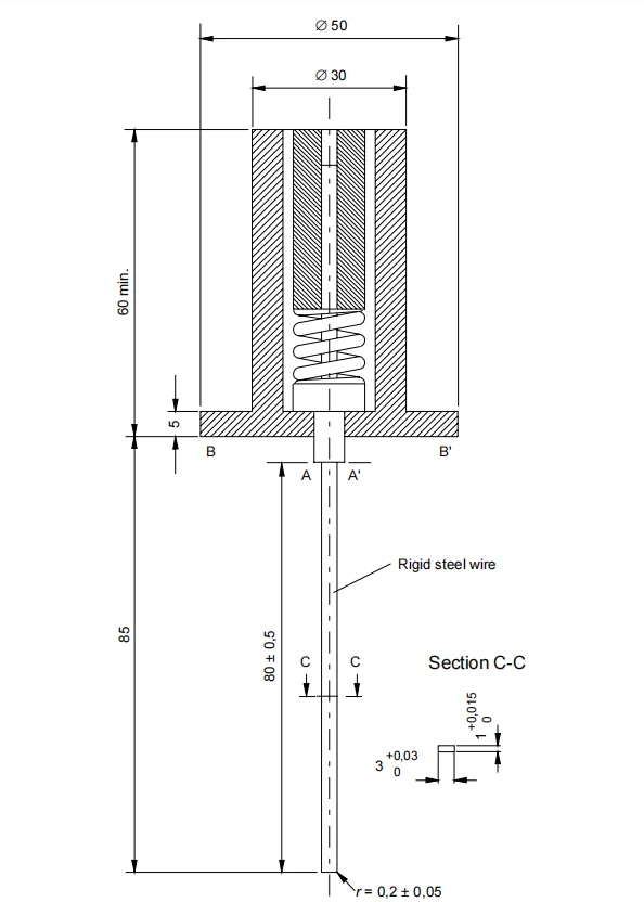
This IEC 60884 socket steel rigid probe carries both of them in one item. The first section is a steel blade pressed against the shutters at 20 N, the probe described in Figure 9. The second is a steel pin applied at 1 N, the probe described in Figure 10. Both sections are rigid and worked by hand, so the force goes into the shutter rather than into a joint or a wrist.
The two forces ask different questions of the same socket. The 20 N blade is the harder push: it tests whether the shutters stay closed when a slim, tool-like object is pressed firmly against them. The 1 N pin is a lighter touch on a much thinner section: it tests whether a narrow object can get past shutters that have already taken a load. Both stages belong to the standard's protection-against-electric-shock check for household and similar electrical appliances, and a laboratory normally reports them together from the same sample.
Socket-outlet and wiring-accessory manufacturers run the probe for their own type tests before a sample goes to an external test house. Third-party laboratories use it to reproduce the clause for a report, importers use it to check the samples they plan to bring to market, and appliance makers use it in incoming inspection. Because the section sizes and the forces are fixed by the figures, the same tool gives the same answer whoever holds it.
The probe is supplied by HERONTEST, a lab test equipment manufacturer working with testing laboratories, socket-outlet manufacturers and equipment importers across Europe, North America and Asia.
| Parameter | Specification |
|---|---|
| Model | HNT-1200 |
| Item type | Steel rigid probe for socket shutter testing |
| Reference standard | IEC 60884, Figure 9 and Figure 10 |
| 20 N probe section | 3 mm × 1 mm steel blade |
| 1 N probe section | Ф1.0 mm steel pin |
| Applied forces | 20 N and 1 N |
| Probe length | 80 mm |
| Probe form | Rigid steel sections, no joint and no adjustment |
| Test directions | Three per probe section |
| Dwell time per direction | About 5 seconds |
Within the electrical plug and socket enclosure safety test, the two applications are aimed at the shutter mechanism of socket-outlets for household and similar purposes — the sprung shutters fitted to keep pins, keys and fingers away from the contacts. They are made at the socket face, with the probe seated against the shutter opening, and the result describes the shutter and the faceplate that carries it.
This is not an enclosure-accessibility check. Work on enclosure openings, whether it is about a finger reaching an opening or a rod or wire passing through it, is done inside the opening with other probes. The shutter tool is applied to a mechanism that is designed to move, which is why the two applications are specified as they are.
A probe is a measuring tool rather than an approval. It gives the shutter test its defined section and its defined force so the result is repeatable and can be reported, and the certification decision stays with the body assessing the product. A shutter that passes the two applications has cleared this check; other clauses in the same assessment are tested with their own tools.
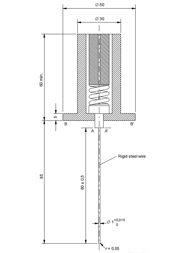
Both working ends of this probe are solid steel: the blade used for the 20 N stage and the pin used for the 1 N stage. The sections are rigid — no joint, no hinge, no spring and no adjuster between the handle and the part that enters the socket — so the result comes from the section size the figure fixes and the force you apply, rather than from a mechanism that can wear, slip or need re-setting.
Nothing has to be assembled, tensioned, adjusted or calibrated before a test. A probe that arrives in its case goes straight to the socket face: check that the blade and the pin are clean and undamaged, then apply the force by hand along the axis of the section as the test procedure sets out. There is no scale to set, no spring pressure to trim, no battery and no display to zero, and nothing to re-check between the 20 N stage and the 1 N stage. A rigid steel gauge needs no start-up routine.
What does need looking after is the working profile. Keep the blade edge and the pin tip true, keep the probe dry, and keep it out of the shared tool box: a section that has been dropped or bent is replaced rather than straightened, because a straightened blade no longer carries the cross-section Figure 9 asks for. Wipe both ends after a session so nothing is carried onto the next faceplate, and store the item where the thin pin cannot be leaned on.
Choosing the right item starts with your requirement, not the catalogue. Our technical team works with buyers in Europe, North America and Asia to match a model to the clause or test condition you have to satisfy, and stays with you afterwards for commissioning, setup and troubleshooting. If an instrument already in service needs attention, we can supply replacement parts and advise on returning it to work. OEM and ODM requests go to the same team.
The wider steel blade is the 20 N section and corresponds to Figure 9; the thin pin is the 1 N section and corresponds to Figure 10. They are applied as two separate stages of the same shutter check.
No. The IEC 60884 socket steel rigid probe stays in the orientation it was inserted with, and no rotation is made while force is applied. Turning the blade moves the load onto the shutter edge, and the reading then no longer belongs to the Figure 9 application.
Contact between the probe and a live part of the socket is the failure. In the electrical plug and socket enclosure safety test the shutter has failed if the metal section reaches a live contact, whether that happens at the 20 N stage or at the 1 N stage.
No. Both working sections are solid steel with no joint, hinge or spring, and there is nothing to assemble, tension or adjust before a test. Keep the blade and the pin from knocks so the sections stay true to the figure they are made to.
The two applications are aimed specifically at shutter mechanisms. A socket-outlet without shutters is assessed against other requirements in the standard, so it is worth confirming which check your sample needs before the probe is used on it.