Technical parameters:
1. Probe length: 100mm
2. Probe diameter: 2.5mm
3. Ball diameter: 35mm
4. Handle diameter: 10mm
5. Handle length: 100mm
6. According to IEC61032 Figure 3 (Test probe C), IEC60529

Rigid test rod C is the probe a laboratory reaches for when an enclosure has to be shown as IP3X. This is the IEC 61032 3N rigid test rod C — the 2.5 mm rod built to IEC 61032 Figure 3 and IEC 60529, supplied as the version whose test calls for a push of 3 ± 0.3 N.
In the hand it is a small, straight, hand-held tool rather than an instrument you switch on. It is applied to the openings of a housing, and the result comes from where the rod goes and how hard it is pressed. That is why the test it is bought for, not the look of the tool, decides which version ends up in the kit.
What the rod produces is an answer rather than a reading of its own: whether a slim probe, pushed with the specified force, can reach a hazardous part through an opening. That answer is what a test report, a type-test file or an enclosure design review is built on.
Physically the probe follows the figure — a slim metal rod, a ball between rod and grip, and a cylindrical handle, in the proportions listed in the specification table below, finished plainly enough that knocks and marks show instead of being hidden.
Between tests it sits in the IP kit beside the 1.0 mm rigid wire D, the jointed test finger B and the pin probes. As an IEC standard test equipment supplier we supply the rod on its own, so a laboratory can replace exactly the probe it needs for the protection level it is working to.
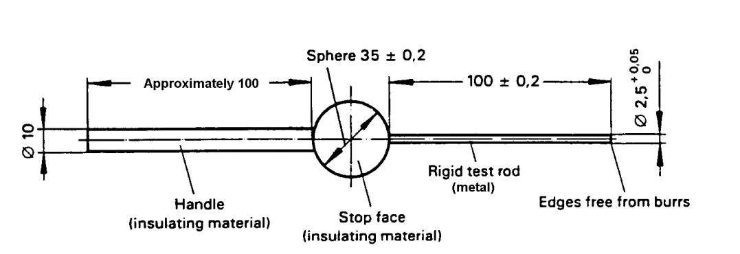
| Model | HNT-PCT |
|---|---|
| Probe designation | Test probe C — rigid test rod, 2.5 mm |
| Reference standard | IEC 61032 Figure 3 (test probe C); IEC 60529 |
| Applied thrust | 3 ± 0.3 N |
| Probe length | 100 mm |
| Probe diameter | 2.5 mm |
| Ball diameter | 35 mm |
| Handle diameter | 10 mm |
| Handle length | 100 mm |
| Simulates | Tools and metal wires in the access test |
| IP characteristic covered | First characteristic numeral 3; additional letter C |
| Supplied as | Single probe, ready to use |
The shape of the rod is only half of what IEC 61032 Figure 3 describes. In the access test the rod has to be pressed into the opening with a thrust of 3 ± 0.3 N, and the check is only valid if that force is really applied and held while the rod goes in.
That is why this rod exists as a product in its own right: it is bought for the test that fixes the push. Matching the rod letter is the easy part; remembering that the clause also fixes a force is what catches people out.
In practice the thrust is applied along the axis of the opening, not at an angle, and it is kept on throughout the insertion. The value should build as a steady pressure rather than arrive as a jab — reaching the figure for a moment and releasing it does not reproduce the condition the clause describes.
The tolerance band matters in both directions. A lighter push makes the check easier than the standard intends and can clear an opening that should fail. A heavier one can flex a shutter, a gasket or a thin panel and produce a reading that belongs to the test set-up rather than to the enclosure.
Because the value has to be demonstrated, the force is normally confirmed on a calibrated push-pull gauge rather than judged by hand, and the reading is written into the test notes beside the result. Where an enclosure is being type tested, that record is what lets a colleague or an assessor repeat the check.
For 3N force IP3X ingress protection testing, the rod itself does nothing clever, and as an IEC standard test equipment supplier we keep it that way: no adjustment between tests, no warm-up, nothing to zero. The values that decide the result are the force you apply and the depth the rod reaches, and both come down to how the probe is handled.
This rod belongs to a family of access probes that most laboratories buy together, because the protection levels tested on a single product run into one another.
Its closest relative is the plain 2.5 mm rod C: the same rod, ball and handle dimensions, supplied for checks where the clause does not fix an applied force. Where a test plan says only that the rod is to be applied to the opening, that is the item; where it quotes a thrust to be held, this is the one.
Moving through the IP code, the 1.0 mm rigid test wire D covers the IP4X access check, and the 12 mm jointed test finger B covers IP2X, where the tool has to reproduce a finger rather than a wire. Because the finger is articulated and the rod is not, the two are not interchangeable, even when they are applied to the same opening.
Pin probes are a separate case again: the short and long test pins are pointed-tool probes used to reach live parts inside Class 0 and Class II equipment, and they work to their own figures rather than to the IP numerals.
Keeping the set together is what most laboratories do, and it is how an IEC standard test equipment supplier builds the range: one rod diameter per level, one ball size and one handle format, so the tools lie in the same case and a technician moving from an IP2X check to an IP3X check picks up the next probe without re-learning the grip.
The rod has nothing to adjust and no wearing part, so its condition between tests is what keeps an IP3X result worth recording. The checks that matter take a couple of minutes, and they only work if they are done the same way every time instead of when something already looks wrong.
After each test
Wipe the rod, ball and handle with a dry, lint-free cloth before the probe goes back in its case — skin oils and fine dust are what collect on the 2.5 mm section, and a cloth takes them off without disturbing the surface. Do not soak the probe or leave it standing on a wet bench. Lay it in the cut-out it came in rather than loose on a bench where a screwdriver or a spanner can roll across the tip. Never use the rod to clear swarf out of a hole, prise open a stiff shutter, fish out a cable or lever a cover: that load is far above anything the test applies, and a rod bent that way cannot be straightened back to the figure. If the probe is dropped onto a hard floor, set it aside and check it before it goes into another test.
Checking the rod before a test that will be reported
Roll the rod slowly across a flat bench and watch the 2.5 mm section against the light; a bend shows as a sliver of daylight that travels along the length. Sight down the rod as a second check. Run a fingertip along the tip and around the ball for a burr or a nick, because a raised edge changes the diameter at the point of contact. Feel the rod-to-ball and ball-to-handle junctions for movement — any slack there changes the line the thrust travels along. Hold what you see against the dimensions your clause names. If anything is out, bring the spare rod into service before the test rather than after it, and write the condition of the probe beside the result so a later reader of the record knows which tool produced it. A laboratory running a continuous test programme is better off keeping a second rod in the kit; a replacement ordered mid-project is the delay a spare prevents.
Handled this way, the probe presents the same condition for 3N force IP3X ingress protection testing on the next enclosure and the one after that, and the record of each check stays comparable with the last.
Choosing the right item starts with your requirement, not the catalogue. Our technical team works with buyers in Europe, North America and Asia to match a model to the clause or test condition you have to satisfy, and stays with you afterwards for commissioning, setup and troubleshooting. If an instrument already in service needs attention, we can supply replacement parts and advise on returning it to work. OEM and ODM requests go to the same team.
Test rod C is the access probe for the IP3X check. It reproduces the tools and metal wires an enclosure is expected to keep out, and it is used on the openings of a housing to see whether anything hazardous — a live part or a dangerous mechanical part — can be reached. In the IP code it serves the first characteristic numeral 3 and the additional letter C.
No — each protection level has its own tool. IP4X is checked with the 1.0 mm rigid test wire D, and IP2X with the 12 mm jointed test finger B, which is articulated because that clause has to reproduce a finger rather than a rigid wire. The 2.5 mm rod C covers the IP3X access check, and on this version the check is run as 3N force IP3X ingress protection testing, with the thrust applied and held.
Any opening that could give access to a live part or a hazardous mechanical part: vents and louvres, gaps around doors and covers, cable entries, and the seams between assembled parts. The rod is applied to each of them with the thrust the clause specifies, with the enclosure standing in the position it is used in.
Treat it as a measuring tool rather than a piece of shop equipment. Keep the rod and ball clean and dry, lay it down instead of dropping it into a toolbox, and never use it as a lever or a pry bar against a metal edge — a bent rod or a burred tip changes the diameter the test depends on. Before a test that will be reported, sight along the rod for a bend and run a finger over the tip for a nick; if either is there, the rod should be replaced rather than straightened.
The ball sits between the 2.5 mm rod and the handle and acts as the guard: everything in front of it is the rod that enters the opening, and the hand stays behind it. It also makes this probe easy to pick out on a bench full of test tools, since the rod itself is only 2.5 mm across.