Technical parameters:
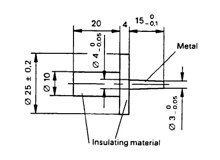
1. Probe diameter: head 3mm, tail 4mm
2. Probe length: 15mm
3. Diameter of baffle: 25mm
4. Thickness of baffle: 4mm
5. Reference standard: IEC61032: 1997 Figure 9

The IEC 61032 Test Pin Probe 13 — also written as test probe 13, or simply the figure 9 short pin — answers one narrow, practical question: can a screwdriver or a similar pointed tool touch a live part inside this equipment? The pin stands in for the tool. A technician works it into the openings an enclosure presents, and the check passes only if the metal tip never reaches anything live.
Physically it is a short stepped metal pin set into a matte white insulating body, with a flanged disc at the rear. Its length is what earns it the short-pin name in the family: it is made for the openings a person could actually poke a tool into, not for deep internal reach. Two diameters meet at the step — a smaller leading head that enters first and a wider tail behind it — and the flange sits between the operator's hand and the opening.
Day to day this is a bench tool rather than a machine. It lives in the probe case of a compliance laboratory, an appliance maker's own test room or a production QA bench, and it is picked up whenever an enclosure has to be shown to close its own openings to a pointed tool. It is also the pin that gets reordered as a straight replacement when a lab's existing pin has been dropped, bent or worn out in the middle of a project.
As an industrial test probe manufacturer, Herontest supplies this pin alongside the rest of the IEC and UL probe range, so a laboratory can cover its finger, rod, wire and pin probes in a single order rather than four.
| Property | Value |
|---|---|
| Model | HNT-P13 |
| Reference standard | IEC 61032:1997, figure 9 |
| Probe designation | Test probe 13 |
| Probe head diameter | 3 mm |
| Probe tail diameter | 4 mm |
| Probe length | 15 mm |
| Baffle diameter | 25 mm |
| Baffle thickness | 4 mm |
| Pin material | Metal |
| Body material | Insulating material |
| Simulated object | Screwdriver or similar pointed tool |
| Equipment classes covered | Class 0 and Class II |
| Purpose of the check | Confirm that live parts cannot be touched |
The equipment class decides whether a pin like this is the right tool for the job. Class II equipment is the double-insulated kind, marked on the rating plate with a double square: protection comes from the insulation, there is no earth connection, and nothing in the installation can be relied on to save a user who reaches a live part. Class 0 equipment takes the same idea further, with no provision for protective earthing at all, so basic insulation and the enclosure are the only barriers. In both cases there is no earth path to fall back on, which is why accessibility is judged so closely.
That is the situation a Class II equipment internal live parts test is designed to probe. With the sample set up as it would be in normal use, the pin is taken to every opening in the enclosure and the question is a single one: can a pointed tool get through to something live? If it can, the enclosure has failed the accessibility requirement, however well the rest of the product performs.
Working on equipment of these classes changes the emphasis of the check rather than the tool. You are not testing how much force a housing withstands or whether it keeps dust out; you are testing whether the openings a user can see and reach are actually closed to a tool. That is why the same pin serves a small double-insulated adapter and a large appliance alike — what changes between them is the enclosure, the openings it presents, and the angles the pin can be worked at.
Depth stop and hand guard
The disc at the rear of the pin sits between the metal pin and the insulating body. It is wider than any opening this pin is meant to enter, so the pin can only travel as far as the disc allows: you lead with the head, work the pin into the opening, and stop when the disc meets the enclosure. That contact sets the insertion depth, which means the same pin seats to the same depth in the same opening whoever is holding it, and readings stay comparable from one technician or one shift to the next. The disc is also a hand guard — your fingers stay behind it while the pin is in place, away from the sharp edge of the opening, and you grip the insulating body rather than the metal. The articulated finger probe carries a 50 mm baffle for the same reason; this disc is sized to the small apertures the short pin is applied to.
Checks before a test
Inspect the pin before it goes into a test, and again after any drop. Start with the head: the leading diameter is what decides whether the pin enters an opening, so a burr, a nick or a flattened tip changes the very geometry the result rests on. Look along the step and the tail for deformation, then check the disc — a disc that is bent or dented no longer seats flat, so the pin can sit at an angle or travel past the depth the flange is meant to set. Examine the insulating body for cracks and feel the joint between pin and body for play; a pin that rocks in its body changes the angle of approach and makes a result hard to defend. Set a doubtful pin aside instead of using it — a record taken with a damaged probe will not hold up if the test is ever questioned, and the pin is the least expensive part of the exercise. Keep it in its case with nothing pressing on the tip, and never loose in a drawer among other steel tools, where one knock against a harder edge is enough to spoil the leading diameter. Where a laboratory runs tests back to back, keep a spare pin on the bench so a damaged one can be swapped out and the test repeated on the same day.
Choosing the right item starts with your requirement, not the catalogue. Our technical team works with buyers in Europe, North America and Asia to match a model to the clause or test condition you have to satisfy, and stays with you afterwards for commissioning, setup and troubleshooting. If an instrument already in service needs attention, we can supply replacement parts and advise on returning it to work. OEM and ODM requests go to the same team.
If your clause cites IEC 61032 figure 9, or names test probe 13, this is that pin. It is the short member of the pin probe family, used for the openings a pointed tool could actually be poked into during normal use rather than for deep internal reach. If your clause names a different figure, send us the reference and we will confirm which pin matches it.
It proves accessibility. A pass means a screwdriver-sized pointed tool cannot reach a live part through any opening in the enclosure. It says nothing about dust, water, insulation strength or earth continuity, which are checked with other probes and instruments. On Class 0 and Class II equipment, where there is no earth connection to protect the user, that accessibility result is the one the enclosure has to deliver.
It does two jobs. It is a depth stop, because the disc is wider than the openings the pin is meant to enter, so the pin cannot travel further in once the disc meets the enclosure. It is also a hand guard: you hold the insulating body, and your fingers stay behind the disc, away from the edge of the opening, while the pin is in place.
No thrust value is set for the figure 9 short pin — the figure defines the pin itself, not a force applied through it. Force-controlled probes are supplied for clauses that specify a thrust in newtons; if your clause names one, tell us and we will point you to the configuration that applies.
Look at the tip first: it should be straight, free of burrs and free of nicks, because a damaged tip changes the diameter that enters the opening. Check that the head, the tail and the disc have not been deformed by an earlier drop, and set the pin aside if anything is doubtful — a result recorded with a damaged probe will not stand up. Between tests, keep it in its case with nothing pressing on the metal tip.