Technical parameters:
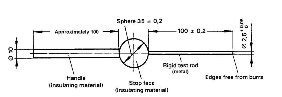
1. Probe length: 100mm
2. Probe diameter: 2.5mm
3. Ball diameter: 35mm
4. Handle diameter: 10mm
5. Handle length: 100mm
6. According to IEC61032 Figure 3 (Test probe C) or IEC60529

Test rod C is the rigid rod used in an IP3X protection degree probe test. It is made to IEC 61032 Figure 3 (test probe C) and called up by IEC 60529, where it serves the first characteristic numeral 3 and the additional letter C — the access side of an ingress-protection assessment rather than the dust or water side.
A slender rod projects from a spherical collar and a cylindrical grip, so the IEC 61032 Test Rod C holds the standard geometry in the technician's hand and stays steady while a controlled thrust is applied to the enclosure. It is a hand tool built for repeat work: the same rod carries a whole test campaign without its geometry changing.
Buyers for this rod usually sit in one of three places. Third-party testing and certification laboratories use it when a clause names probe C and the assessor expects the standard figure to be reproduced exactly. In-house safety and QC labs at household-appliance, lighting, electronics and power-tool manufacturers keep one on the bench for design verification and pre-certification self-checks. Production and incoming-inspection teams use it for a quick enclosure check before a formal test is booked. It is also ordered as a straight replacement when a rod is lost, damaged or no longer matches the drawing issued with the original test plan.
Day to day the rod lives with the rest of the IP probe set and works on its own or beside the other probes in the family when a project covers more than one numeral. It needs no setting up: check that the rod is straight and the tip undamaged, and it is ready for the next opening.
| Parameter | Value |
|---|---|
| Designation | Test probe C (rigid test rod C) |
| Reference | IEC 61032 Figure 3; IEC 60529 |
| Test level | First characteristic numeral 3; additional letter C |
| Probe diameter | 2.5 mm |
| Probe length | 100 mm |
| Ball diameter | 35 mm |
| Handle diameter | 10 mm |
| Handle length | 100 mm |
| Applied thrust | 3 ± 0.3 N |
| Simulates | Straight tools and metal wires |
| Model reference | HNT-PC |
Test rod C is rigid, and that is deliberate. It does not bend or articulate, so it reproduces the straight-line form the standard calls for and transfers the applied thrust to the tip instead of flexing away from it. Jointed fingers are used for other checks and behave differently on purpose; here, straightness is the property under test.
The rod is finished as a slender polished metal pin seated in a white cylindrical handle, with a spherical collar between the two. The handle gives the technician control over angle and thrust during a force-controlled test and stays in the hand when the rod is pressed against a vertical or overhead surface, while the collar keeps the fingers clear of the rod itself and marks where the probe geometry ends.
Each unit is finished and checked against its stated dimensions before packing, as you would expect from a standard compliant test probe manufacturer. The rod is made to the figure rather than to a free drawing, so the tool that arrives is dimensioned the way the standard writes it.
Ordinary care keeps a probe in working order. Before a test campaign, sight along the rod to confirm it is straight and check the tip for burrs or flat spots; after handling, wipe the metal dry and return the rod to its protective sleeve so the tip is not knocked against other tools. A bent or blunted rod no longer reproduces the figure and should be replaced rather than straightened.
| Designation element | What it covers | How it is checked |
| IP3X — access numeral | Whether a straight tool or a length of wire can reach a hazardous part inside the enclosure | This rigid rod, applied at 3 ± 0.3 N as the IP3X protection degree probe test requires |
| IPX3 — water numeral | Whether water sprayed at an angle finds its way into the enclosure | Spray nozzles, an oscillating-tube rig or similar spray equipment; no probe takes part in this test |
| The digit on its own | The number 3 appears in both designations but stands for two different checks | Read which position the digit occupies in the designation before ordering anything |
| X | That characteristic is left unspecified by the clause | Nothing is tested or claimed for it — a rod cannot produce a water rating |
| Additional letter C | The access check applied to a part or opening named in the clause | The same rigid rod; only the place it is applied changes |
| Dust numerals | Dust ingress, a characteristic separate from access | Dust test equipment rather than a probe |
| Your clause wording | The clause, not the tool, decides which test you owe | Send the designation exactly as your standard writes it and note which side of it you need, so the quotation covers the right equipment |
Choosing the right item starts with your requirement, not the catalogue. Our technical team works with buyers in Europe, North America and Asia to match a model to the clause or test condition you have to satisfy, and stays with you afterwards for commissioning, setup and troubleshooting. If an instrument already in service needs attention, we can supply replacement parts and advise on returning it to work. OEM and ODM requests go to the same team.
They are different positions in an IP designation, and this rod belongs to the first one. In an IP3X protection degree probe test the 3 is the access numeral — protection against reaching a hazardous part with a tool or a wire — while the X marks a characteristic the clause does not specify. Water spray sits in the second numeral and is carried out with spray equipment, not with a probe. If your requirement is the water test, this is not the tool you need.
It is the shoulder that stops the rod at the enclosure surface. Because the ball is wider than the opening under test, only the rod enters, so insertion depth is set by the probe geometry rather than by how hard the operator pushes. That is what makes the result repeatable from one opening, and one technician, to the next.
The rod is made to the geometry of the figure rather than to a generic pin, so the probe diameter, the probe length and the position of the shoulder are the ones a report reviewer will check. If your assessor asks for a dimensional record to travel with the shipment, tell us what form it should take and we will confirm what can be arranged.
It can be applied by hand, but probe C is a force-controlled test and hand pressure varies between operators, which is the first thing a reviewer questions. Many laboratories hold the rod in a thrust dynamometer or a spring-loaded holder so the force is applied and read the same way on every opening. The rod's rigid construction transfers that force to the tip without flexing, so the reading reflects the test rather than the tool.
No. The additional letter C is a tool-access check and the same rigid rod carries it. What changes is where the check is applied — the clause names the part or opening — and where the pass/fail line sits, which also comes from the clause. A laboratory that already holds a rod for the numeral 3 work does not need another tool for the letter.