Technical parameters
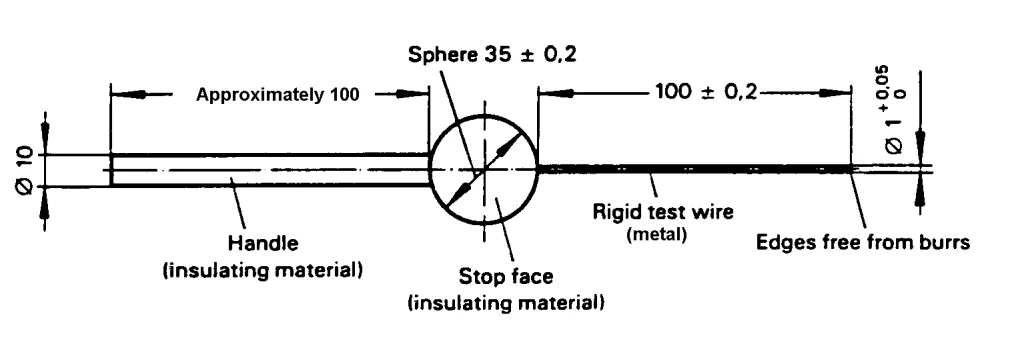
1.Test Probe Length :100mm
2. Test Probe Diameter:1.0mm
3.Dam- sphere Diameter:35mm
4.Handle Diameter:10mm
5.Handle Length 100mm
6. According to IEC61032 figure 4 (the Test probe D)

The IEC 61032 1N Test Wire D is the force-controlled version of test probe D. A 1.0 mm rigid metal wire is carried on a 35 mm sphere and a 100 mm handle, and the probe is used to check whether an opening in an enclosure lets a thin rigid wire reach hazardous live parts. Its geometry follows IEC61032 Figure 4 (test probe D) and the dimensions published in IEC61032:1997 and IEC60529:2001, and the same probe form is used in UL appliance work. In the appliance industry it is the standard tool for the IP4X electrical safety probe test, the protection-against-electric-shock check on domestic and similar electrical appliances.
What separates it from the plain 1.0 mm wire is the thrust. The access requirement at the fourth characteristic numeral is written around a defined 1 N force rather than around whatever pressure a technician happens to apply, so this probe is supplied for that wording: the wire is brought to the opening and the 1 N thrust is applied and held through the insertion. Two engineers working from the same clause, on the same enclosure, then reach the same conclusion, which is what a test record has to show. Where a clause names only the wire, the plain rigid wire probe performs the same physical check; where it names a force, this is the version to order.
The probe is a mechanical gauge, not an instrument. It carries no measurement electronics; what it provides is a defined wire, a defined sphere and a defined force, so the same check can be repeated in a manufacturer's own test room, an incoming inspection bay or a third-party laboratory and still mean the same thing.
In use it stays in the hand. There is no fixture, no power supply and no software to run: the technician guides the rigid wire into each opening, applies the thrust and watches whether the wire touches anything live.
| Model reference | HNT-PDT |
| Probe designation | Test probe D (rigid test wire D) |
| Reference standard | IEC61032:1997, Figure 4 |
| Companion standard | IEC60529:2001; also applied in UL work |
| Probe length | 100 mm |
| Probe diameter | 1.0 mm |
| Dam-sphere diameter | 35 mm |
| Handle diameter | 10 mm |
| Handle length | 100 mm |
| Applied thrust | 1 N |
| Access level covered | IP4X |
| Form | Handheld rigid wire probe |
Probe D is a handheld tool, and most of it stays outside the enclosure. The working part is the 1.0 mm rigid wire at the front; the 35 mm sphere sits between the wire and the handle and forms the front face of the tool; and the handle runs 100 mm at a 10 mm diameter, wide enough to grip firmly while the thrust is applied and long enough to keep a technician's fingers clear of the panel.
The construction is deliberately simple. Nothing has to be set or adjusted before a test, because the probe's behaviour comes from the wire being straight and the sphere being the right size, both of which a laboratory can confirm with a micrometer and a caliper.
The wire is the part that wears. It is what meets edges, burrs and sharp mouldings, and it is what to inspect after a heavy day or a dropped probe. A nick or a bend is not a cosmetic problem on this tool: it changes what the opening sees.
Photographs of the probe show the thin metal wire tip, the smooth white spherical guard and the cylindrical handle, with a coiled lead running from the handle through a right-angle connector.
Day-to-day care is short. Wipe the wire and the guard with a soft dry cloth after use rather than leaving workshop dust on the surfaces, and store the probe where nothing can press on the wire: a case or a foam-lined drawer is enough. Do not use the wire as a lever or a scraper, and keep it out of a bag where other tools can knock it.
Because the geometry is fixed, the probe holds its setting from one test to the next. That is why the wire diameter and the sphere are the two values a laboratory checks most often, and why a replacement is ordered by designation and dimensions rather than by eye.
| Household and similar appliance laboratories | The access check on finished enclosures before a product is booked for certification |
| Manufacturers' in-house test rooms | Pre-test self-checks, so a design issue is found before a laboratory booking is made |
| Third-party test houses | Reproducing the wire D check for a report on a client's appliance |
| Design and development engineers | Testing a new vent, seam or switch cut-out on a prototype |
| Laboratories building an IP set | Adding the fourth access level to the finger and rod they already hold |
| Importers and distributors | Verifying incoming appliance batches against the same criterion |
| Tooling and production QC | Confirming that a moulding change has not opened a new path to live parts |
Choosing the right item starts with your requirement, not the catalogue. Our technical team works with buyers in Europe, North America and Asia to match a model to the clause or test condition you have to satisfy, and stays with you afterwards for commissioning, setup and troubleshooting. If an instrument already in service needs attention, we can supply replacement parts and advise on returning it to work. OEM and ODM requests go to the same team.
It is test probe D of IEC61032:1997, drawn to Figure 4. Laboratories use it with IEC60529:2001 for the access-to-hazardous-parts requirement at the fourth characteristic numeral, and the same probe form appears in North American appliance work. Check the edition and figure named in your own clause, because that wording is what your report will be measured against.
Yes. Wire D belongs to the same access series as rod C, the jointed finger B and the pin probes, and the finger, rod and wire cover the IP2X to IP4X steps between them. As a safety accessibility probe supplier we build the whole access range to its own figure and dimensions, so the finger, the rod, the wire and the pins can be specified together for one laboratory.
The probe is brought to the opening and the 1 N force is applied and held while the wire enters, and the same value is kept as the probe is angled through each orientation the opening allows, rather than tapping the wire in and letting the force drop away. A thrust gauge or the force fixture your procedure names makes an IP4X electrical safety probe test easier to keep consistent from one opening to the next. Durations and the exact orientations come from your edition of the standard, so follow that wording in the test record.
Diameter and level. Wire D carries a 1.0 mm wire for the fourth access step, while rod C carries a 2.5 mm rod for the third. An opening that admits a 1.0 mm wire is not the same opening that admits a 2.5 mm rod, which is exactly why the two levels are run separately, and each probe is ordered by the figure your clause names.
It is the guard and the stop. The sphere meets the mouth of the opening and limits how far the wire can travel into the enclosure, so the check measures whether access is possible rather than how deep the wire reaches. It also keeps the hand a consistent distance from the panel while the thrust is held, which makes the push easier to repeat opening after opening.
Keep the wire straight and the measuring surfaces clean. A quick check of the wire diameter and the sphere with a caliper, plus a look along the wire for bends, covers most sessions, and a probe that has been dropped or used as a lever should be inspected before it goes back into a test. Wipe it with a soft dry cloth and store it where nothing can press on the wire, such as a case or a foam-lined drawer, and it will hold its geometry between checks.